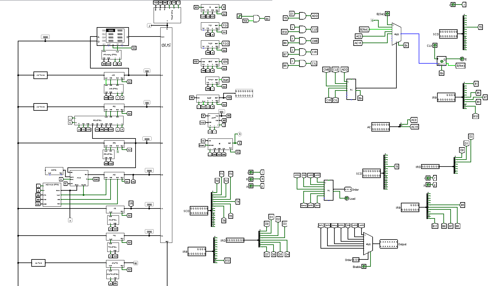
Logisim Moris Mano Computer
This project is part of a Computer Organization course and aims to design a functional CPU, enabling it to solve mathematical problems and run simple programs.
The Morris Mano Basic Computer was designed using Logisim, a digital circuit design and simulation tool. Logisim provides a visual environment for designing, simulating, and testing digital circuits.
You can see the project code along with the work report on GitHub.
Hardware Components
The Morris Mano Basic Computer consists of the following hardware components:
- Memory Unit: 4096 words, each 16 bits wide.
- Registers: Nine registers including AR (Address Register), PC (Program Counter), DR (Data Register), AC (Accumulator), IR (Instruction Register), TR (Temporary Register), OUTR (Output Register), INPR (Input Register), and SC (Sequence Counter).
- Flip-Flops: Seven flip-flops representing various control and status flags: I (Interrupt), S (Stop), E (Enable), R (Read/Write), lEN (Input Enable), FGI (Input Flag), and FGO (Output Flag).
- Decoders: Two decoders: a 3 x 8 operation decoder and a 4 x 16 timing decoder.
- 16-bit Common Bus: Used for data transfer between different components.
- Control Logic Gates: Responsible for control signals generation and management.
- Adder and Logic Circuit: Connected to the input of the Accumulator (AC) for arithmetic and logical operations.


